The Raspberry Pi Pico has a flexible set of GPIO (General Purpose Input/Output) pins that allow it to interface with various sensors, modules, and devices. Here’s an overview of the GPIO pin details and their functions:
Key Specifications
- GPIO Pins: 26 multi-function GPIO pins (labelled
GP0toGP28, withGP23,GP24, andGP25used internally). - Digital I/O: Each pin can be used as a digital input or output.
- Analog Input: Three GPIOs (26, 27, and 28) support analog input with a 12-bit ADC (Analog-to-Digital Converter).
- Voltage Levels: All GPIOs operate at 3.3V (they are NOT 5V tolerant).
- I2C, SPI, UART: Pins can be configured for communication protocols like I2C, SPI, and UART.
- PWM: Pulse Width Modulation (PWM) can be generated on almost all GPIOs.
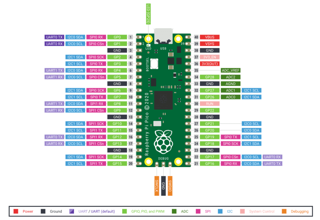
Pin Diagram Overview
| GPIO Pin | Function (Default) | Notes |
|---|---|---|
| GP0-GP1 | I2C0 (SDA, SCL) | Default pins for I2C0 |
| GP2-GP3 | SPI0 (CS, SCK) | Default pins for SPI0 |
| GP4-GP5 | SPI0 (TX, RX) | Default SPI data pins |
| GP6-GP7 | UART1 (TX, RX) | Default UART1 TX/RX pins |
| GP14-GP15 | I2C1 (SDA, SCL) | Default pins for I2C1 |
| GP16-GP19 | SPI1 (CS, SCK, TX, RX) | Default pins for SPI1 |
| GP26-GP28 | ADC (ADC0, ADC1, ADC2) | Only pins with analog (ADC) support |
| GP25 | LED (Onboard) | Connects to the onboard LED |
| VSYS | Power Input | Accepts 1.8V to 5.5V input for powering the board |
| 3V3(OUT) | 3.3V Output | Provides 3.3V for external components |
| GND | Ground | Common ground for circuits |
| RUN | Reset Input | Resets the microcontroller when shorted to ground |
Special Functions on GPIO Pins
- I2C: There are two I2C buses, which can be mapped to multiple pins.
- Default Pins:
- I2C0:
GP0(SDA) andGP1(SCL) - I2C1:
GP14(SDA) andGP15(SCL)
- I2C0:
- Default Pins:
- SPI: There are two SPI interfaces.
- Default Pins:
- SPI0:
GP2(CS),GP3(SCK),GP4(TX),GP5(RX) - SPI1:
GP16(CS),GP18(SCK),GP19(TX),GP17(RX)
- SPI0:
- Default Pins:
- UART: Two UART interfaces are available (UART0 and UART1).
- Default Pins:
- UART0:
GP0(TX) andGP1(RX) - UART1:
GP4(TX) andGP5(RX)
- UART0:
- Default Pins:
- ADC (Analog-to-Digital Converter):
- Only
GP26,GP27, andGP28support analog input. - The ADC resolution is 12 bits, with an input range from 0 to 3.3V.
- Only
- PWM (Pulse Width Modulation): PWM is supported on almost all GPIOs, allowing for tasks such as controlling motor speed or LED brightness.
Power and Ground Pins
- VSYS: Supplies power to the Pico, with an acceptable input voltage range of 1.8V to 5.5V.
- 3V3(OUT): Provides a 3.3V output (up to ~300mA), which can be used to power external components.
- GND: Ground pins for completing the circuit.
GPIO Configuration in MicroPython
The Pin class in MicroPython is used to control General Purpose Input/Output (GPIO) pins on microcontrollers. This class provides methods to configure pins as inputs, outputs, or to handle alternative functions like PWM, I2C, UART, and SPI, depending on the hardware’s capabilities.
Basic Usage of the Pin Class
from machine import PinPin Class Constructor
pin = Pin(id, mode=-1, pull=-1, value=None, drive=0, alt=-1)- id: Specifies the GPIO pin number or name, depending on the board. For example,
Pin(25)on the Raspberry Pi Pico refers to GPIO 25, which controls the onboard LED. - mode: Sets the pin mode. It can be:
Pin.IN: Configure the pin as an input.Pin.OUT: Configure the pin as an output.Pin.OPEN_DRAIN: Configure the pin as an open-drain output.
- pull: Configures the internal resistor. Options are:
Pin.PULL_UP: Pull-up resistor enabled.Pin.PULL_DOWN: Pull-down resistor enabled.None: No internal resistor.
- value: Optional, sets the initial output value (only applicable if the mode is
Pin.OUT). - drive: Sets the pin drive strength. Not available on all boards.
- alt: Configures an alternate function (PWM, I2C, UART, etc.) if supported by the hardware.
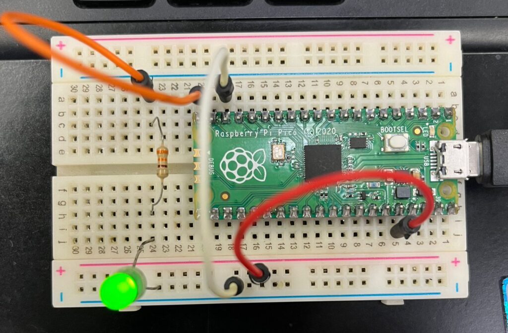
Example # 1 – Blink an LED
Circuit Diagram
Code in MicroPython
from machine import Pin  # Import the Pin class from the machine module
import time              # Import the time module for delays

# Set up GPIO 15 as an output pin (adjust if using a different pin for your LED)
led = Pin(15, Pin.OUT)   # Create a Pin object for GPIO 15 and set it as an output

# Infinite loop to blink the LED
while True:
    led.value(1)         # Turn the LED on by setting the output to high (1)
    time.sleep(1)        # Wait for 1 second (LED stays on)

    led.value(0)         # Turn the LED off by setting the output to low (0)
    time.sleep(1)        # Wait for 1 second (LED stays off)
Explanation
- Import Modules:
from machine import Pin: Imports thePinclass, which allows you to control GPIO pins.import time: Imports thetimemodule for creating delays between LED state changes.
- Pin Setup:
led = Pin(15, Pin.OUT): Initializes GPIO 15 as an output pin for controlling the LED. Change the pin number (15) if you’re using a different GPIO.
- Main Loop:
while True: Creates an infinite loop to keep the LED blinking.led.value(1): Sets GPIO 15 to high, turning the LED on.time.sleep(1): Waits for 1 second, keeping the LED on.led.value(0): Sets GPIO 15 to low, turning the LED off.time.sleep(1): Waits for 1 second with the LED off.
This code will make an external LED blink with a 1-second interval between on and off states.
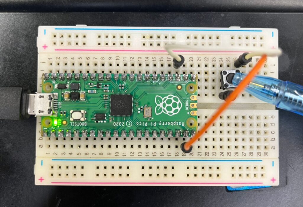
Example # 2 – LED Blink on PushButton
Circuit Diagram
Code in MicroPython
from machine import Pin  # Import the Pin class from the machine module

# Initialize GPIO pins
led = Pin(25, Pin.OUT)           # Set up GPIO 25 as an output pin for the LED (On Board LED)
button = Pin(14, Pin.IN, Pin.PULL_UP)  # Set up GPIO 14 as an input pin with a pull-up resistor for the button

# Infinite loop to check button state and control LED
while True:
    if button.value() == 0:      # Check if the button is pressed (value is 1)
        led.value(1)             # Turn the LED on
    else:
        led.value(0)             # Turn the LED off when the button is released
Explanation
- Import Modules:
from machine import Pin: Imports thePinclass for controlling GPIO pins.
- Pin Setup:
led = Pin(15, Pin.OUT): Initializes GPIO 15 as an output pin to control the LED.button = Pin(14, Pin.IN, Pin.PULL_DOWN): Initializes GPIO 14 as an input pin with an internal pull-down resistor to ensure a stable low state when the button is not pressed.
- Main Loop:
while True: Creates an infinite loop to continuously check the button state.if button.value() == 1: Checks if the button is pressed (the value reads1when pressed).led.value(1): Turns the LED on if the button is pressed.
else: If the button is not pressed (value == 0), it turns the LED off.
This code will keep the LED on only while the button is pressed. Once the button is released, the LED will turn off.

