Introduction to ADC Peripheral on Raspberry Pi Pico
The Raspberry Pi Pico has a 12-bit SAR ADC (Analog-to-Digital Converter) peripheral, which allows it to measure analog signals. This ADC module can convert an analog voltage (0-3.3V) to a digital value ranging from 0 to 4095, providing sufficient resolution for many sensor and variable resistor-based applications. In this example, we’ll use the ADC to read values from a variable resistor (potentiometer) connected to the Pico.
Components Needed
To complete this project, you’ll need the following:
- Raspberry Pi Pico
- Variable Resistor (10k potentiometer)
- Jumper Wires
- Breadboard (optional)
Circuit Diagram
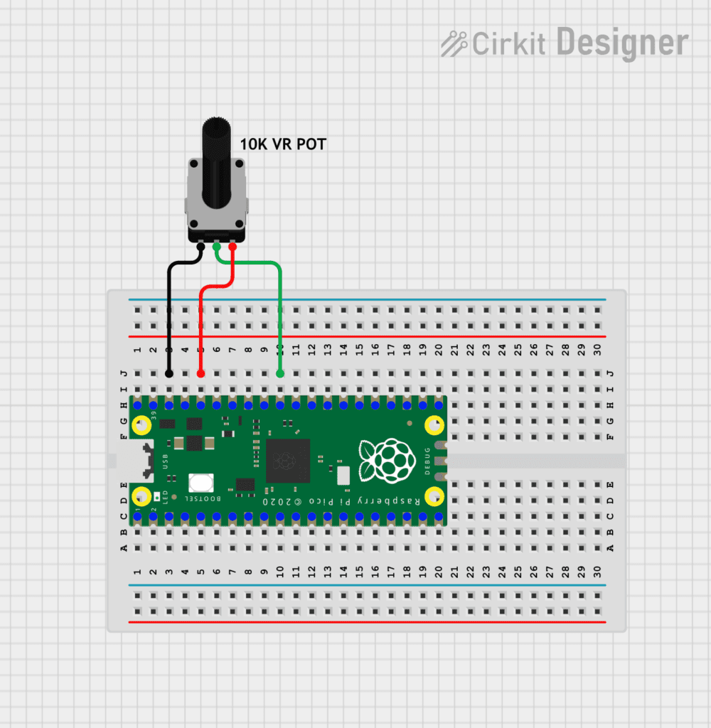
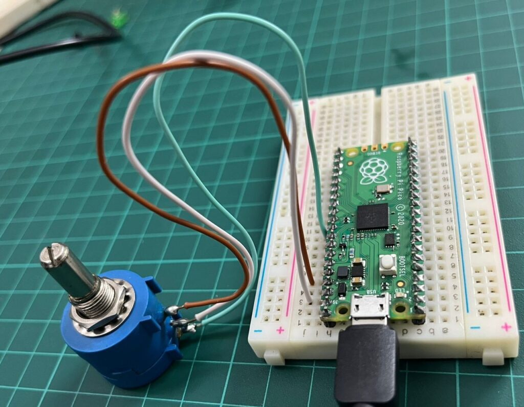
- Connect the VCC (3.3V) pin of the Pico to one terminal of the variable resistor.
- Connect the GND of the Pico to the other terminal of the variable resistor.
- Connect the wiper (middle terminal) of the variable resistor to GP26 (ADC0) on the Pico.
Here’s a quick reference for the connections:
| Potentiometer Pin | Raspberry Pi Pico Pin |
|---|---|
| VCC (3.3V) | 3V3 (Pin 36) |
| GND | GND (Pin 38) |
| Wiper (Output) | GP26 (Pin 31) |
This setup allows the ADC0 on GP26 to read the variable resistor’s output voltage, which will vary based on the position of the potentiometer’s slider.
Code to Read ADC Data
With the wiring complete, we can now write code in MicroPython to read the data from the potentiometer and display it on the serial console.
from machine import ADC, Pin
import time

# Initialize ADC on GP26 (ADC0)
potentiometer = ADC(Pin(26))

while True:
    # Read ADC value (0-4095)
    adc_value = potentiometer.read_u16()

    # Convert to voltage (0-3.3V)
    voltage = adc_value * 3.3 / 65535

    # Print ADC and voltage value to serial
    print("ADC Value:", adc_value, " Voltage:", "{:.2f}".format(voltage), "V")

    # Wait before next reading
    time.sleep(0.5)
Explanation of the Code
- ADC Setup:
- We initialize the ADC object on GP26 (ADC0) using
ADC(Pin(26)). This sets up the Pico to read analog signals from the specified pin.
- We initialize the ADC object on GP26 (ADC0) using
- Reading the ADC Value:
- Inside the
whileloop, we read the ADC value from the potentiometer usingpotentiometer.read_u16(). Theread_u16()method returns a 16-bit value (0-65535) for improved precision across different platforms, though the Pico’s ADC is technically 12-bit.
- Inside the
- Converting to Voltage:
- To convert the ADC value to a voltage, we use the formula: voltage=adc_value×3.365535\text{voltage} = \frac{\text{adc\_value} \times 3.3}{65535}voltage=65535adc_value×3.3
- Here,
3.3represents the reference voltage of the Pico, and65535is the maximum possible value fromread_u16(). This gives us a voltage reading between 0 and 3.3V.
- Printing the Results:
- The
print()statement displays both the ADC value and the corresponding voltage on the serial console. "{:.2f}".format(voltage)formats the voltage to two decimal places for easy readability.
- The
- Loop with Delay:
time.sleep(0.5)adds a delay of 0.5 seconds between readings, so the values don’t update too rapidly on the console. Adjust this delay as needed for real-time monitoring.
Output
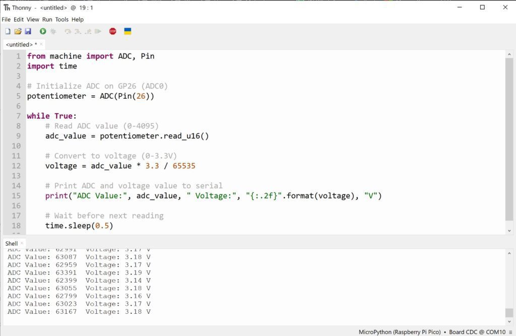
The fluctuations you’re seeing can be caused by a few factors, including electrical noise, poor connections, or the potentiometer not being stable. Here are some ways to stabilize the readings:
1. Use Averaging to Smooth Out the Readings
Adding an averaging technique can help reduce noise. By taking multiple readings and averaging them, we can get a more stable value.
Here’s how you could modify the code to include averaging:
from machine import ADC, Pin
import time

# Initialize ADC on GP26 (ADC0)
potentiometer = ADC(Pin(26))

def read_average(num_samples=10):
    total = 0
    for _ in range(num_samples):
        total += potentiometer.read_u16()
        time.sleep(0.01)  # Small delay between readings
    return total // num_samples

while True:
    # Take an averaged reading
    adc_value = read_average(num_samples=10)

    # Convert to voltage (0-3.3V)
    voltage = adc_value * 3.3 / 65535

    # Print ADC and voltage value to serial
    print("ADC Value:", adc_value, " Voltage:", "{:.2f}".format(voltage), "V")

    # Wait before next averaged reading
    time.sleep(0.5)
In this code:
- The
read_averagefunction takes 10 samples and calculates the average. You can increase the sample count if you still see fluctuations. - A slight delay (
time.sleep(0.01)) between readings allows for a more stable result.
2. Ensure Good Connections
Verify the potentiometer is connected properly:
- Ground and VCC lines should be stable and connected directly to the Pico.
- Use solid connections to avoid fluctuations due to loose wires.
3. Filter Using a Capacitor
Adding a capacitor between the ADC input pin (GP26) and GND can help filter out high-frequency noise. A capacitor of around 0.1 µF to 1 µF can be suitable for smoothing the input.
4. Shield from Noise
If your setup is near other electronic devices, this could induce noise. Placing the circuit away from such devices or using shielded cables for connections may help reduce interference.
Important Fact about ADC Ref. Voltage on PICO Kit
The RP2040 ADC does not have an on-board reference and therefore uses its own power supply as a reference.
On Pico the ADC_AVDD pin (the ADC supply) is generated from the SMPS 3.3V by using an R-C filter (201Ω into 2.2μF). This is a simple solution but does have the following drawbacks:
- 1. We are relying on the 3.3V SMPS output accuracy which isn’t great
- 2. We can only do so much filtering and therefore ADC_AVDD will be somewhat noisy
- 3. The ADC draws current (about 150μA if the temperature sense diode is disabled, but it varies from chip to chip)and therefore there will be an inherent offset of about 150μA*200 = ~30mV. There is a small difference in currentdraw when the ADC is sampling (about +20μA) so that offset will also vary with sampling as well as operatingtemperature.
Changing the resistance between the ADC_VREF and 3V3 pin can reduce the offset at the expense of more noise – which may be OK especially if the use case can support averaging over multiple samples.
Driving high the SMPS mode pin (GPIO23), to force the power supply into PWM mode, can greatly reduce the inherent ripple of the SMPS at light load, and therefore the ripple on the ADC supply. This does reduce the power efficiency of the board at light load, so the low-power PFM mode can be re-enabled between infrequent ADC measurements by driving GPIO23 low once more.
The ADC offset can be reduced by tying a second channel of the ADC to ground, and using this zero-measurement as an approximation to the offset.
For much improved ADC performance, an external 3.0V shunt reference, such as LM4040, can be connected from the ADC_VREF pin to ground. Note that if doing this the ADC range is limited to 0-3.0V signals (rather than 0-3.3V), and the shunt reference will draw continuous current through the 200Ω filter resistor (3.3V-3.0V)/200 = ~1.5mA.
Note that the 1Ω resistor on Pico (R9) is designed to (maybe) help with shunt references that would otherwise become unstable when directly connected to 2.2μF. It also makes sure there is a little filtering even in the case that 3.3V and ADC_VREF are shorted together (which is a valid thing to do if you don’t care about noise and want to reduce the inherent offset).
Finally, R7 is a physically large 1608 metric (0603) package resistor, so can be relatively easily removed if a user wants to isolate ADC_VREF and do their own thing with the ADC voltage, for example powering it from an entirely separate voltage (e.g. 2.5V). Note that the ADC on RP2040 has only been qualified at 3.0/3.3V but should work down to about 2V.
Summary
This project demonstrates how to set up and read analog data using the ADC peripheral on the Raspberry Pi Pico. By connecting a potentiometer to the ADC0 (GP26) pin, we can read and display the variable output voltage on the serial console. This code and circuit form the basis for integrating more complex analog sensors or building responsive projects based on analog inputs with the Pico’s ADC.
This approach can be expanded to other ADC pins and analog sensors, enabling versatile applications with the Raspberry Pi Pico in MicroPython.

