The Raspberry Pi Pico’s power chain is designed for flexible power delivery, allowing it to be powered via USB, batteries, or other external sources. This flexibility is supported by a combination of regulators, filters, and monitoring systems that work together to ensure stable operation for the RP2040 microcontroller and other components.
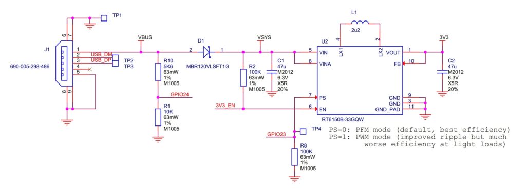
Power Components
- VBUS (5V Input):
VBUS is the 5V input from the micro-USB port, the primary source when the Pico is connected via USB. This voltage is directed through a Schottky diode (D1) to produce VSYS, which serves as the main system input voltage. - VSYS (Main System Input Voltage):
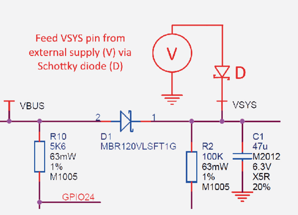
VSYS is generated from VBUS after passing through D1, allowing for “power ORing,” a method that lets multiple power sources be combined safely. VSYS feeds the entire board and powers the main voltage regulator. Here is an example for power ORing (Source: Linear Technology Datasheet).
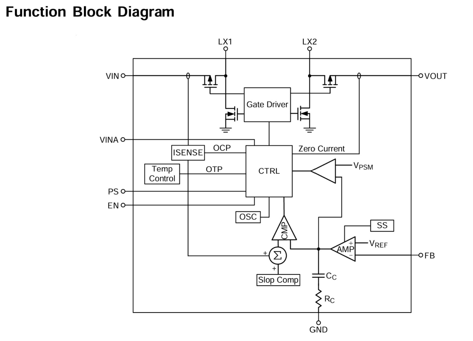
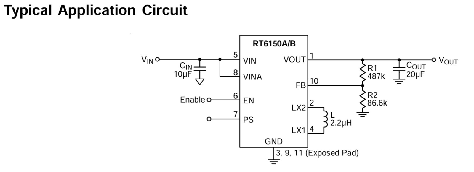
- RT6150 Buck-Boost Switching Mode Power Supply (SMPS):
VSYS is then fed into the RT6150 SMPS, a buck-boost regulator that can adjust between buck (step-down) and boost (step-up) modes to provide a stable 3.3V output. This output powers the RP2040 microcontroller, its I/O, and any external circuits that might require 3.3V.- Voltage Regulation: The buck-boost converter maintains a 3.3V output even if VSYS varies between approximately 1.8V and 5.5V. This allows flexibility in the choice of power sources, making it ideal for battery operation where the voltage might fluctuate.
- Power Save Mode (PS): GPIO23 controls the Power Save (PS) pin on the SMPS. By default, PS is low, placing the SMPS in Pulse Frequency Modulation (PFM) mode. In PFM, the regulator uses power-saving techniques, only activating the switching MOSFETs when needed to keep the output stable. Setting PS high forces the SMPS into Pulse Width Modulation (PWM) mode, which, while less power-efficient, reduces output ripple under light loads, beneficial for certain sensitive applications.
- VBUS Monitoring and VSYS Disabling:
GPIO24monitors the presence of VBUS. Resistors R10 and R1 ensure that VBUS is pulled down to 0V when VBUS is absent, providing accurate monitoring of USB connection status.- SMPS EN Pin: The EN (enable) pin for the SMPS is connected to VSYS through a 100kΩ pull-up resistor. This pin can be accessed on Pico pin 37. Shorting this pin to ground will disable the SMPS, putting the board into a low-power state if needed.
- Filtering and Voltage Monitoring:
VSYS is R-C filtered and divided by three through R5, R6, and C3 components. This filtered VSYS value is monitored on ADC channel 3, which allows for a basic battery voltage monitoring setup. By reading this ADC channel, users can estimate the supply voltage, providing insight into battery health when the Pico is powered by an external battery.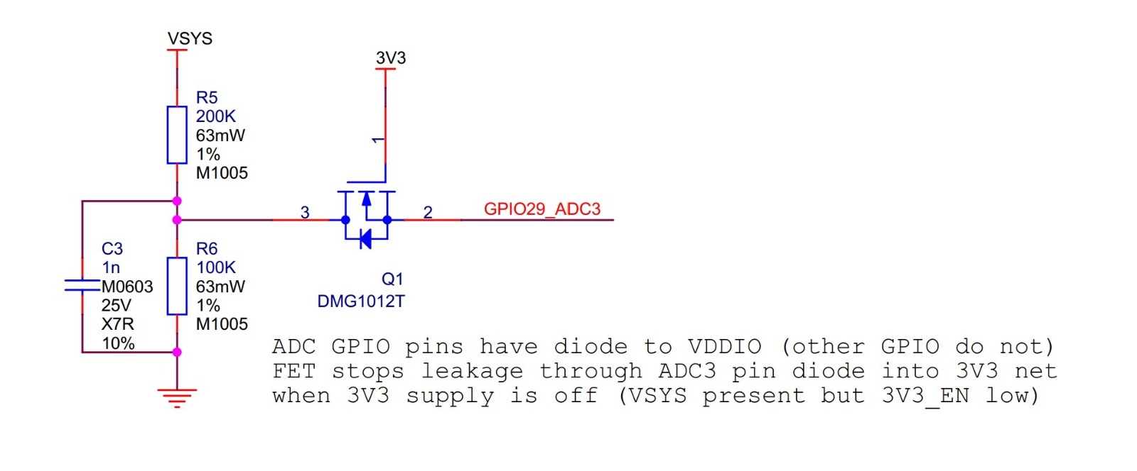
Summary of Power Management
- Schottky Diode (D1): Allows safe switching between different power sources.
- RT6150 SMPS: Regulates VSYS to 3.3V output, adapts to varying input voltages (1.8V-5.5V).
- PFM and PWM Modes: Adjusts power consumption based on load; controlled via
GPIO23. - VBUS Monitoring: Checks for USB connection status using
GPIO24. - Voltage Monitoring: Provides battery monitoring capability via ADC3.
Example Use Case: Battery-Powered Mode
In battery-powered mode, the Raspberry Pi Pico’s power chain ensures stable operation even as battery voltage fluctuates. Here’s how it works:
- VSYS and SMPS:
When running on a battery, the input voltage (VSYS) feeds into the RT6150 buck-boost SMPS (Switched-Mode Power Supply). This SMPS is designed to regulate the power from a wide input range (1.8V to 5.5V), so even if the battery voltage drops below the usual operating voltage, it can still output a steady 3.3V. This feature allows the Pico to operate reliably even when battery levels are low, ideal for applications with limited power sources. - Battery Monitoring:
The Pico’s ADC channel 3 is connected to VSYS through a resistor-capacitor (R-C) divider, allowing it to read the battery voltage. This gives a rough measurement of the battery’s charge level, so the device can detect when the battery is running low. For instance, as the battery depletes, the ADC readings will decrease, indicating it might be time to recharge or replace the battery. - Power Efficiency:
When in battery mode, the power chain defaults to Pulse Frequency Modulation (PFM), reducing power consumption at light loads by only switching on the SMPS as needed. This helps conserve energy and extend battery life, making the Pico well-suited for low-power applications like sensor nodes or portable devices.
Powering Up Pico
The simplest way to power Pico is to plug in the micro-USB, which will power VSYS (and therefore the system) from the 5V USB VBUS voltage, via D1 (so VSYS becomes VBUS minus the Schottky diode drop).
If the USB port is the only power source, VSYS and VBUS can be safely shorted together to eliminate the Schottky diode drop (which improves efficiency and reduces ripple on VSYS).
If the USB port is not going to be used, it is safe to power Pico by connecting VSYS to your preferred power source (in the range ~1.8V to 5.5V).
IMPORTANT!!
If you are using Raspberry Pi Pico in USB Host mode (e.g. using one of the TinyUSB host examples) then you must power Pico by providing 5V to the VBUS pin.
Power up direct on VSYS Via Schottky Diode
The simplest way to safely add a second power source to Pico is to feed it into VSYS via another Schottky diode (see Figure 16). This will ‘OR’ the two voltages, allowing the higher of either the external voltage or VBUS to power VSYS, with the diodes preventing either supply from back-powering the other. For example a single Lithium-Ion cell* (cell voltage ~3.0V to 4.2V) will work well, as will 3×AA series cells (~3.0V to ~4.8V) and any other fixed supply in the range ~2.3V to 5.5V. The downside of this approach is that the second power supply will suffer a diode drop in the same way as VBUS does, and this may not be desirable from an efficiency perspective or if the source is already close to the lower range of input voltage allowed for the RT6150.
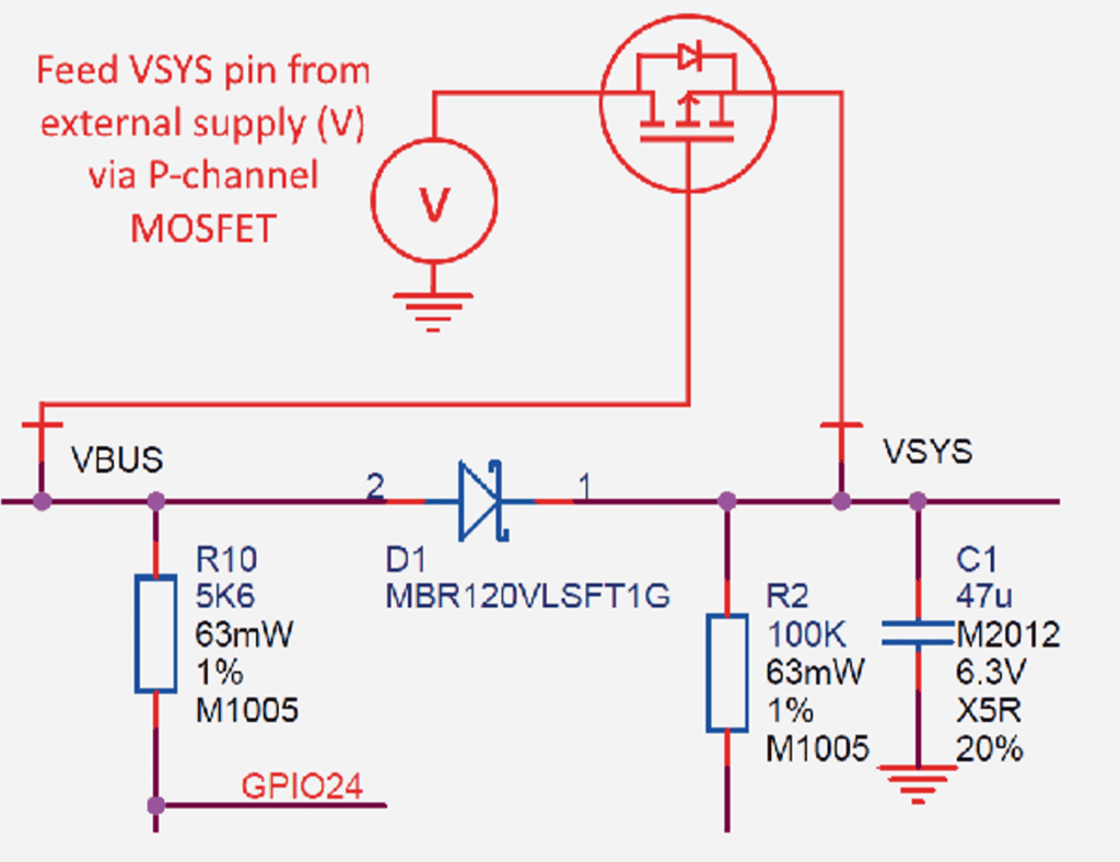
Power up direct on VSYS Via P-Channel Mosfet (Improved and Preffered Way)
An improved way to power from a second source is using a P-channel MOSFET (P-FET) to replace the Schottky diode as shown in Figure 17. Here, the gate of the FET is controlled by VBUS, and will disconnect the secondary source when VBUS is present. The P-FET should be chosen to have low on resistance, and therefore overcomes the efficiency and voltage-drop issues with the diode-only solution. Note that the Vt (threshold voltage) of the P-FET must be chosen to be well below the minimum external input voltage, to make sure the P-FET is turned on swiftly and with low resistance. When the input VBUS is removed, the P-FET will not start to turn on until VBUS drops below the P-FET’s Vt, meanwhile the body diode of the P-FET may start to conduct (depending on whether Vt is smaller than the diode drop). For inputs that have a low minimum input voltage, or if the PFET gate is expected to change slowly (e.g. if any capacitance is added to VBUS) a secondary Schottky diode across the P-FET (in the same direction as the body diode) is recommended. This will reduce the voltage drop across the PFET’s body diode. An example of a suitable P-MOSFET for most situations is Diodes DMG2305UX which has a maximum Vt of 0.9V and Ron of 100mΩ (at 2.5V Vgs).
CAUTION!!
If using Lithium-Ion cells they must have, or be provided with, adequate protection against over-discharge, overcharge, charging outside allowed temperature range, and overcurrent. Bare, unprotected cells are dangerous and can catch fire or explode if over-discharged, over-charged or charged / discharged outside their allowed temperature and/or current range.
Power up direct on VSYS Via P-Channel Mosfet (Improved and Preffered Way)
Pico can also be used with a battery charger. Although this is a slightly more complex use case it is still straightforward. Below Figure shows an example of using a ‘Power Path’ type charger (where the charger seamlessly manages swapping between powering from battery or powering from the input source and charging the battery, as needed).
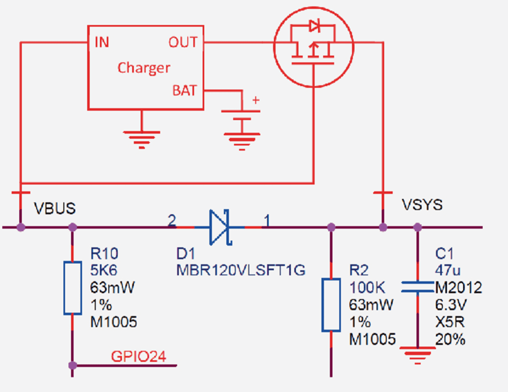
In the example we feed VBUS to the input of the charger, and we feed VSYS with the output via the previously mentioned P-FET arrangement. Depending on your use case you may also want to add a Schottky diode across the P-FET as described in the previous section.

