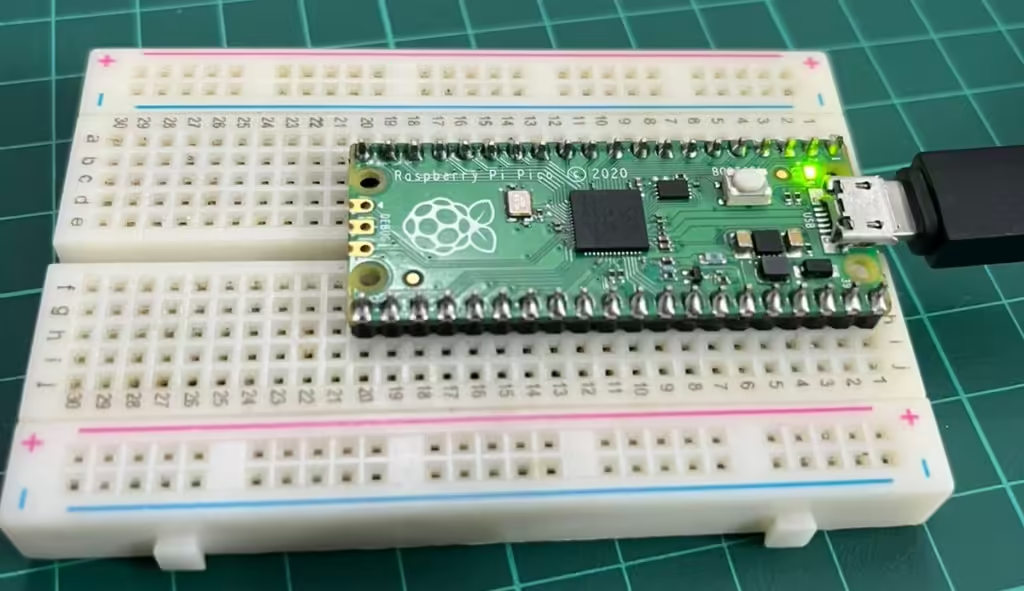
The RP2040 microcontroller, found in devices like the Raspberry Pi Pico, has multiple hardware timers that can count independently and trigger events at precise intervals. In this guide, we’ll explore how timers work and show you how to use them to toggle an LED on and off.
What Is a Timer in the RP2040?
A timer in the context of a microcontroller is a hardware peripheral that counts up (or down) at regular intervals based on a clock source. The RP2040’s timer system includes a 64-bit counter and allows you to set alarms that can trigger events like interrupts—special functions that the CPU executes when specific conditions are met. These alarms are useful for scheduling tasks, such as toggling an LED or running a routine at regular intervals.
In MicroPython, we can access and control these timers, making it easy to perform periodic tasks without manually counting time in code.
Key Timer Concepts
Before we get into coding, let’s clarify a few key concepts:
- Counter: A register that increments (or decrements) with each clock pulse, measuring time.
- Alarm: A threshold value that, when reached, triggers an event or interrupt.
- Interrupt Service Routine (ISR): A function that the CPU runs automatically when an interrupt event occurs.
Setting Up the Timer to Toggle an LED
Let’s use an RP2040 timer in MicroPython to periodically toggle an LED. We’ll use an alarm to generate an interrupt every half-second (500 milliseconds). When the interrupt occurs, it will trigger an ISR that toggles the LED on and off.
Step 1: Prepare Your Hardware
- Connect an LED: If you’re using a Raspberry Pi Pico, you can use the built-in LED on GPIO 25, or connect an external LED to another GPIO pin with a current-limiting resistor (220Ω to 330Ω).
- Install MicroPython: Flash your RP2040 with MicroPython if you haven’t already.
Step 2: Writing the MicroPython Code
Let’s walk through the code to set up the timer, configure the interrupt, and toggle the LED.
- Import Required Modules:
- We need
Timerfrom themachinemodule to set up the timer. - The
Pinclass allows us to control GPIO pins.
- We need
- Define the LED Pin:
- Set up the GPIO pin connected to the LED, either GPIO 25 (for the built-in LED) or another pin you’ve chosen.
- Create the Timer and Interrupt Handler:
- Create a timer object and configure it to trigger an interrupt at a specified interval.
- Define the ISR function that will toggle the LED.
Here’s the complete code:
from machine import Timer, Pin
import time

# Configure LED pin (use GPIO 25 for the built-in LED on the Pico)
led = Pin(25, Pin.OUT)

# Define a variable to store the LED state
led_state = False

# Define the interrupt handler function
def toggle_led(timer):
    global led_state  # Access the led_state variable from within the function
    led_state = not led_state  # Toggle the LED state
    led.value(led_state)  # Set the LED pin to the new state

# Set up a timer to trigger the interrupt every 500 ms
timer = Timer()
timer.init(period=500, mode=Timer.PERIODIC, callback=toggle_led)

# Let the program run indefinitely
while True:
    time.sleep(1)  # Keep the main loop alive

Explanation of the Code
- Defining the LED Pin:
Pin(25, Pin.OUT)initializes GPIO 25 as an output pin to control the LED. - Interrupt Handler (
toggle_led): This function is our ISR. Every time the timer reaches the 500 ms interval, it will calltoggle_led, which toggles the LED state by changingled_stateand updating the pin. - Timer Setup:
Timer()creates a timer object..init(period=500, mode=Timer.PERIODIC, callback=toggle_led)configures the timer to run periodically (every 500 ms) and callstoggle_ledeach time.
How It Works
- Timer Initialization: The timer is configured to generate an interrupt every 500 milliseconds.
- ISR Execution: When the timer reaches the specified interval, it automatically calls
toggle_led, which switches the LED on or off. - Main Loop: Although this code doesn’t require any instructions in the main loop, we include a
while Trueloop withtime.sleep(1)to keep the program running indefinitely.
Testing Your Setup
- Upload the Code: Load the script onto your RP2040 using Thonny or any MicroPython-compatible IDE.
- Run the Script: When you run the code, you should see the LED toggling on and off every half-second.
Tips for Experimenting
- Change the Timer Interval: You can adjust the
periodparameter intimer.init(period=500)to other values (e.g., 1000 for one second) to see how the LED toggling speed changes. - Try Other GPIO Pins: You can modify the
ledpin definition to use an external LED on a different GPIO pin. - Add More Tasks: Since the timer runs in the background, you could add other tasks to the main loop.
Summary
In this guide, we explored how to use the RP2040’s hardware timer to trigger an interrupt that toggles an LED in MicroPython. By setting up periodic alarms and using interrupt service routines (ISRs), you can perform time-sensitive operations in the background without constantly monitoring time in your main code. This approach is valuable for applications that require precise timing, such as real-time data logging, signal generation, or controlling external devices.
Now that you understand how timers work, try experimenting with different intervals and actions for the ISR to gain more familiarity with timers on the RP2040!


well explained..